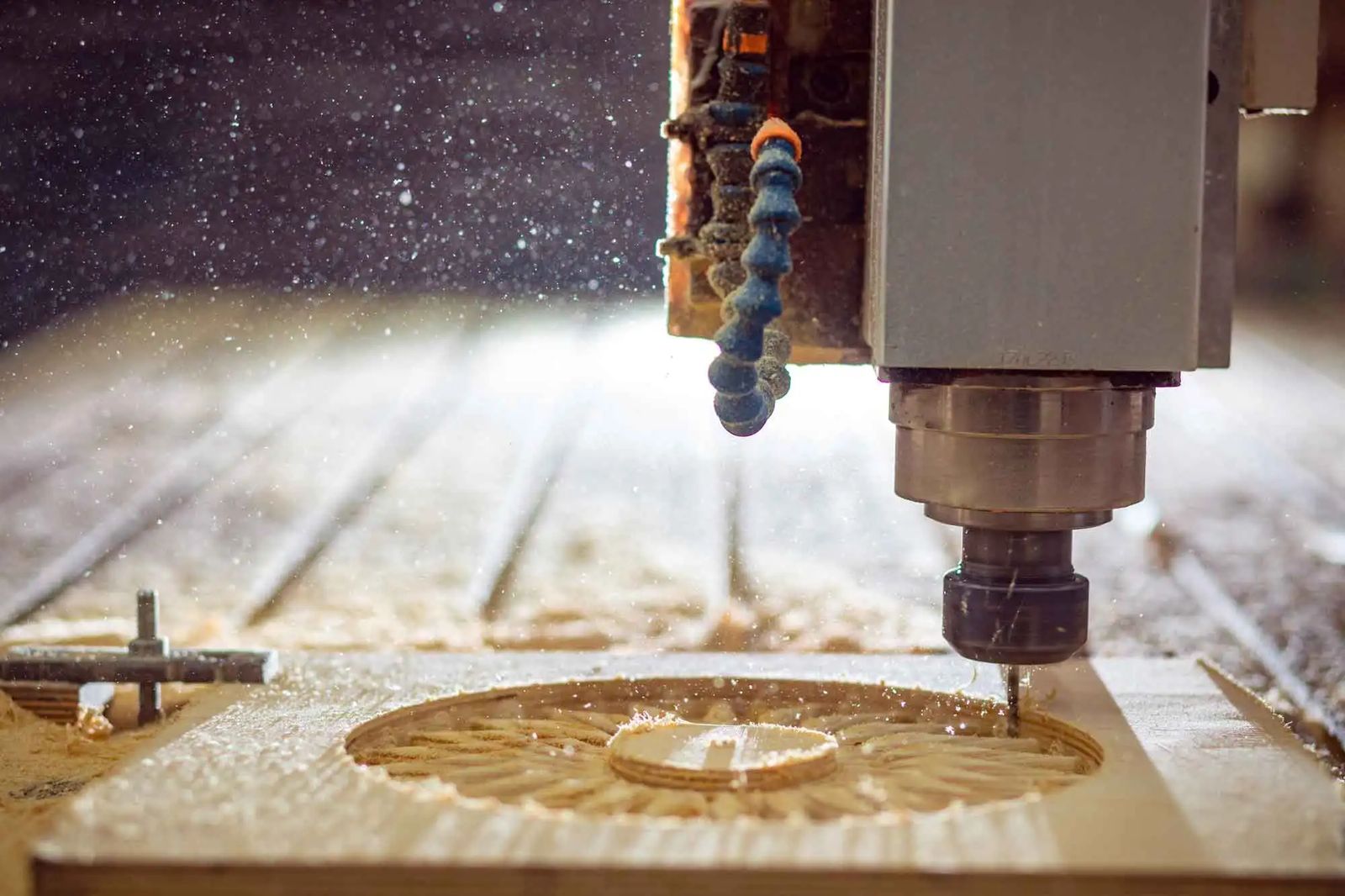
What CNC does in a hardwood component plant
A CNC (computer numerical control) router moves a spinning cutter along paths calculated from a drawing. In a factory that makes furniture parts from beech, oak and ash, it does the work that used to need a row of specialised machines and a lot of jigs: cutting parts to size and to curved outlines, drilling dowel and fitting holes, milling grooves and mortises, profiling edges, engraving decoration and carving reliefs.
The value is repeatability. A chair leg or a stair tread cut on CNC is the same on the thousandth piece as on the first, and a change in the design is a change in the program, not a new set of templates. That makes CNC the bridge between a designer's 3D model and a series of solid wood parts, for small batches as much as for large runs.
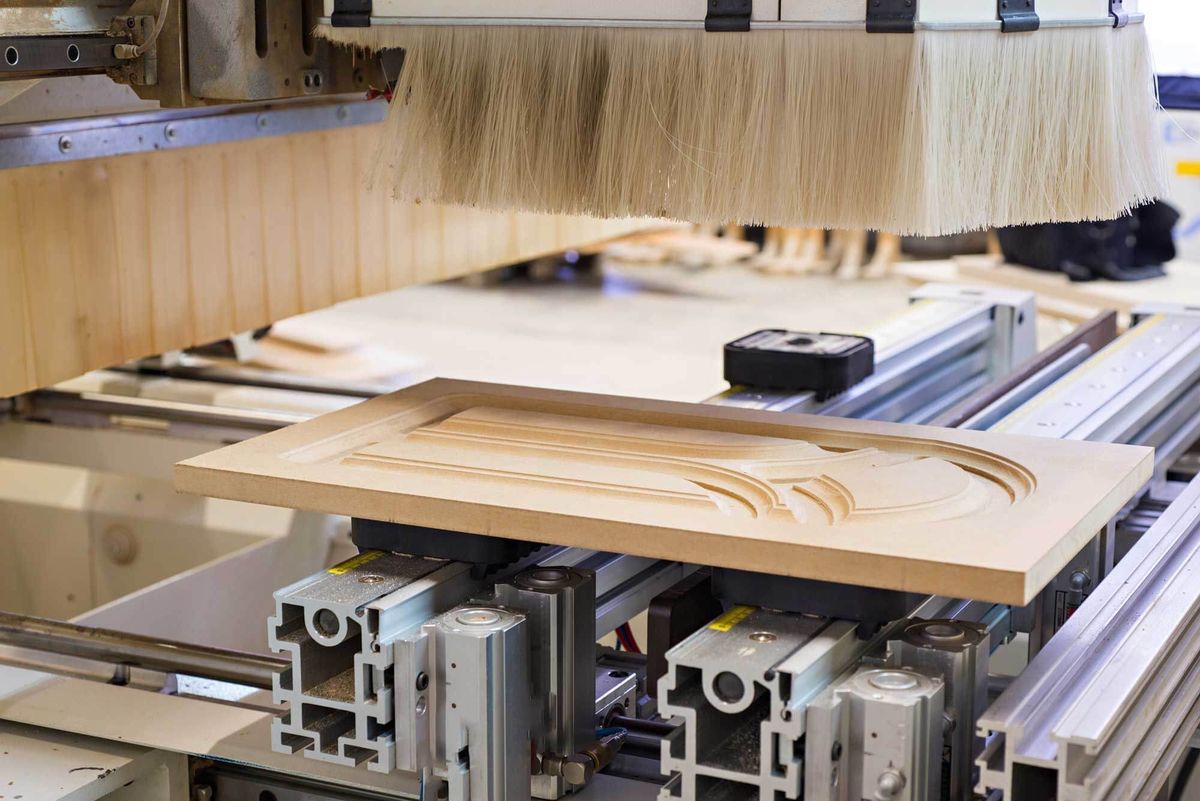
3-axis vs 5-axis: when the extra axes pay off
A 3-axis machine moves the cutter along X, Y and Z, always pointing straight down. It covers flat parts, outlines, pockets, grooves and vertical holes from one side: panels, tops, fronts, flat components and engravings. To work a second face, the part is turned and clamped again.
A 5-axis machine adds two rotary axes, so the cutter can tilt and turn around the part. That changes three things:
- Compound angles. A splayed chair leg meets the seat rail at an angle in two planes. A 5-axis head drills the hole or cuts the mortise at that angle directly.
- 3D surfaces. Curved backrests, saddle seats, armrests and sculpted legs can be contoured with the side of the cutter, which leaves a smoother surface than stepping down with a ball-nose tool.
- Fewer clampings. Several faces can be machined in one set-up. Every re-clamping adds a small positional error, so fewer clampings mean joints that fit more consistently.
For flat and prismatic parts, a 3-axis machine is usually faster and cheaper per piece. The rule of thumb is simple: if the drawing shows angles that are not 90° to the main face, or surfaces that curve in two directions, ask whether the part is planned for 5-axis. The guide to how solid wood chairs are made shows where these parts appear.
Tools: solid carbide, carbide-tipped and diamond
Router cutters for wood come in three main families. Solid-carbide spiral cutters are ground from one piece of cemented carbide: tungsten carbide grains held together by a metal binder, usually cobalt. They are rigid, sharp and suit the high chip loads of CNC work. Carbide-tipped cutters have carbide tips brazed onto a steel body; they are cheaper in large diameters and profile shapes, but for a 12.7 mm cutter in hardwood Freud's chart allows them only about half the chip load of solid carbide.1 Diamond (polycrystalline diamond, PCD) tools last far longer and cost far more, and are used where tool life outweighs tool price.
Spiral geometry matters too. An up-cut spiral lifts chips out of the cut but can lift fibres on the top face; a down-cut spiral pushes fibres down for a clean top edge; compression cutters combine both, for clean top and bottom edges on through-cuts.
Why oak eats tools: tannins and the cobalt binder
Machinists know that oak dulls tools faster than beech of similar hardness. Part of the reason is chemical. A study of carbide tools surfacing green Appalachian oak found that wear begins with tannic acid in the wood attacking the cobalt binder of the carbide; once the binder is weakened, cutting forces tear out the tungsten carbide grains. Replacing the standard 6% cobalt binder with a chromium-cobalt binder gave a fivefold increase in tool life.3
The practical lessons: keep separate tool sets for oak if you can, ask your tool supplier for grades with corrosion-resistant binders, and remember that wet oak is the worst case. Kiln-dried oak at furniture moisture is less aggressive than green timber.
Feeds and speeds: chip load, rpm and cutting speed
The key number in CNC routing is the chip load: the thickness of material each cutting edge removes per revolution. Too small a chip turns into dust, which does not carry heat away from the edge and dulls it prematurely; too large a chip leaves a rough surface.1 The other numbers follow from it:
- Feed rate = spindle speed (rpm) × number of cutting edges × chip load.1
- Cutting speed = π × cutter diameter × spindle speed. It describes how fast the edge moves through the wood.
Freud's starting values for solid-carbide bits in hardwood, at a cutting depth equal to the cutter diameter, run from 0.05–0.13 mm per edge for a 3.2 mm cutter to 0.46–0.53 mm for a 12.7 mm cutter.1 The values for softwood are slightly higher. Both Freud and Onsrud reduce the chip load by at least 25% when the depth of cut is twice the diameter, and by 50% at three times the diameter.1,2
Show the data
| Cutter diameter | Lower value | Upper value |
|---|---|---|
| 3.2 mm (1/8") | 0.05 mm | 0.13 mm |
| 6.35 mm (1/4") | 0.20 mm | 0.28 mm |
| 9.5 mm (3/8") | 0.36 mm | 0.41 mm |
| 12.7 mm (1/2") | 0.46 mm | 0.53 mm |
Reduce by at least 25% at 2× diameter depth and 50% at 3× (Freud, Onsrud). Carbide-tipped bits run lower chip loads. Source: Freud (2017), Router bit feed and speed for CNC, chip-load chart for solid-carbide bits (inches converted to mm).
Tool makers that publish feed charts per tool series use correction factors instead. In Leitz's handbook, feed charts for shank cutters are drawn for a reference material at 18,000 rpm, and the feed rate is multiplied by 0.8 for hardwood or solid wood on most cutters (0.9 on some) and by 0.7–0.8 for cross-grain work.6
Worked example and starting values by cutter diameter
Take a two-edge, 12.7 mm (½") solid-carbide cutter at 18,000 rpm in beech, with a chip load of 0.5 mm, inside Freud's range. The feed rate is 18,000 × 2 × 0.5 mm = 18,000 mm/min, or 18 m/min. Its cutting speed is π × 0.0127 m × 18,000 / 60 ≈ 12 m/s. If the same cutter has to go three times its diameter deep in one pass, the chip load halves and the feed drops to about 9 m/min. (Our calculation with the Freud and Onsrud rules.)1,2
| Cutter diameter | Chip load | Feed, depth 1× diameter | Depth 2× | Depth 3× |
|---|---|---|---|---|
| 3.2 mm | 0.09 mm | 3.2 m/min | 2.4 m/min | 1.6 m/min |
| 6.35 mm | 0.24 mm | 8.7 m/min | 6.5 m/min | 4.3 m/min |
| 9.5 mm | 0.38 mm | 13.7 m/min | 10.3 m/min | 6.9 m/min |
| 12.7 mm | 0.50 mm | 17.8 m/min | 13.4 m/min | 8.9 m/min |
Starting points for test cuts only. Tool makers' data for a specific cutter series take priority. Source: Calculated from Freud (2017) chip loads and the depth rules of Freud (2017) and Onsrud: feed = rpm × edges × chip load.
Treat these as starting points for test cuts, not settings. Machine rigidity, clamping, cutter length and the finish you need all shift the best values, and the tool maker's data for a specific cutter series take priority over any general chart.
Grain direction, tear-out and climb vs conventional milling
Wood is not a uniform material. Its fibres run along the board, and a cutter that lifts them instead of shearing them leaves tear-out: small chunks torn out below the cutting line. Tear-out is worst where the cutter runs against the grain, on curved outlines where the grain direction changes along the path, at exit points across the grain and on interlocked or wavy grain.
- Conventional milling (the cutter's edge moves against the feed direction) is more controlled on manual machines but tends to lift fibres ahead of the cut.
- Climb milling (the edge moves with the feed) shears fibres down onto the part and usually gives a cleaner edge on CNC, where the machine holds the part and the feed rigidly.
- A common strategy is to rough in one direction and finish with a light climb pass, and to plan curved outlines so the cutter runs "downhill" with the grain wherever possible.
- For cross-grain exits, a sacrificial backer or a final pass from the other side prevents the edge from breaking out.
Sharp tools and a correct chip load solve more tear-out than any toolpath trick. A dull edge rubs and lifts fibres; a chip that is too thin burnishes and burns.
Workholding and what tolerance means in wood
Most panels and flat parts are held on a vacuum table, sometimes on a spoilboard; small, curved or narrow parts need dedicated fixtures or vacuum pods. The quality of the clamping sets the quality of the part: a blank that vibrates or moves by a fraction of a millimetre shows it in every joint.
Tolerances in wood are also a question of moisture. A machine can position a cutter to a few hundredths of a millimetre, but the wood keeps moving. European beech shrinks about 11.7% tangentially from green to oven-dry.7 With the Wood Handbook's linear estimate, that means a flat-sawn beech part 500 mm wide changes by roughly 2 mm for every percentage point of moisture content.8 (Our calculation.) A tight tolerance on a drawing therefore only makes sense together with a moisture content at which it is measured. The guide to wood moisture content explains the equilibrium values.
From drawing to part: files and data to send a CNC supplier
CNC programs are made in CAM software from a 2D or 3D model. The format you send decides how much the supplier has to redraw:
- DXF or DWG for 2D outlines, holes and pockets, with layers for each depth or operation.
- STEP (or IGES) for 3D parts. STEP is the most reliable neutral format for solid models.
- PDF drawings with dimensions, tolerances and notes, even when a model is sent. The drawing tells the supplier what matters; the model only tells them the shape.
Mark the critical dimensions, the reference faces, the grain direction and the visible faces. A model with no drawing leaves every one of those decisions to someone who does not know how the part will be used.
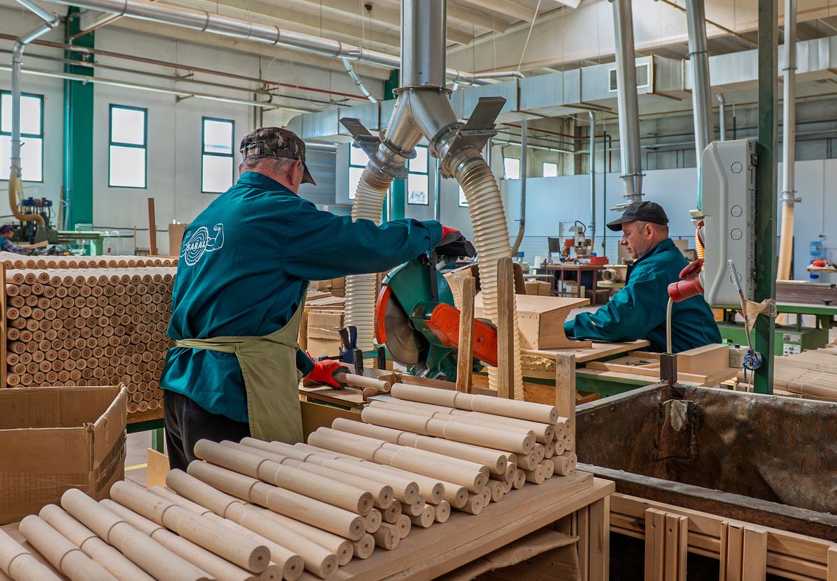
Dust: carcinogen status and the 2 mg/m³ limit
CNC routing, and above all sanding, turns a share of every part into fine dust. The International Agency for Research on Cancer classifies wood dust as carcinogenic to humans (Group 1); adenocarcinoma of the nasal cavities and paranasal sinuses is clearly associated with exposure to hardwood dust. The highest exposures have generally been reported in furniture and cabinet making, with dust levels during machine sanding and similar operations frequently above 5 mg/m³.4
EU law sets a binding occupational exposure limit for hardwood dust, measured as the inhalable fraction over an eight-hour reference period. Directive 2004/37/EC set it at 5 mg/m³.9 Directive (EU) 2017/2398 lowered it to 2 mg/m³, with a transitional limit of 3 mg/m³ until 17 January 2023. Where hardwood dust is mixed with other wood dust, the limit applies to all the wood dust in the mixture.5 As of October 2026, 2 mg/m³ is the binding EU value; national rules may be stricter.
Show the data
| Limit value | |
|---|---|
| Directive 2004/37/EC | 5 mg/m³ |
| Directive 2017/2398, transitional until 17 Jan 2023 | 3 mg/m³ |
| Since 17 Jan 2023 | 2 mg/m³ |
If hardwood dust is mixed with other wood dust, the limit applies to all wood dust in the mixture. Source: Directive 2004/37/EC, Annex III; Directive (EU) 2017/2398, Annex.
Meeting the limit is an engineering task: extraction hoods at every spindle, air speeds sized for the ducts, sealed transport of chips and dust to a separator, and regular measurement. For a buyer, it is also a sign of a well-run plant. Ask a potential supplier how dust is extracted and whether exposure is measured.
How we machine hardwood at SARAL
Checklist for ordering CNC-machined hardwood parts
- Files. 3D model (STEP) or 2D outlines (DXF), plus a dimensioned PDF drawing.
- Material. Species, solid or glued, grade, and whether the supplier provides the wood or machines yours.
- Moisture content. The target moisture of the blanks, and the moisture at which tolerances are checked.
- Tolerances. Only on the dimensions that matter, with reference faces marked. Ask what the supplier can hold and how it is measured.
- Grain and visible faces. Grain direction on each part, which faces are visible and which edges must be free of tear-out.
- Quantities and batches. Prototype, first article, series size and call-off rhythm.
- Surface. Machined only, sanded to which grit, or finished.
- Packaging. Bulk, layered or kitted per product; labelling and protection of edges.
- Health and safety. How dust is extracted and whether exposure is measured, especially for a long-term supplier.
Frequently asked questions
What feed rate should I use for hardwood on a CNC router?
Start from the chip load: for a 12.7 mm, two-edge solid-carbide cutter in hardwood, 0.46–0.53 mm per edge, which gives about 16–19 m/min at 18,000 rpm.1 Reduce the chip load by 25% at a depth of twice the diameter and by 50% at three times, then refine with test cuts.1,2
Do I need a 5-axis machine for wooden furniture parts?
Not for flat or prismatic parts, which a 3-axis machine makes efficiently. A 5-axis machine pays off on parts with compound angles or double-curved surfaces, such as splayed chair legs, curved backrests and armrests.
Why does oak dull router bits faster?
Oak's tannic acid chemically attacks the cobalt binder of carbide tools, after which the carbide grains break out. A chromium-cobalt binder gave five times the tool life in tests on green oak.3
What is the legal limit for hardwood dust in the EU?
2 mg/m³ of inhalable dust over an eight-hour reference period, binding since 17 January 2023 under Directive (EU) 2017/2398. When hardwood dust is mixed with other wood dust, the limit applies to all of it.5